Motor Speed Control Circuit Diagram
Scr controller cmos eleccircuit Motor control ac induction circuit speed diagram phase single electronic iron soldering motors make diy electrical schematics board technology las Controller pwm ne555 controle circuits controlador circuitstoday velocidad usando arduino stepper amplifier diy diagrams timer variador
Wiring Diagram For A Dayton 4x796 Motor Speed Control
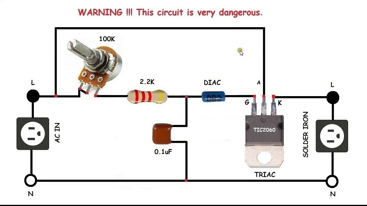
Triac motor speed control circuit diagram Scr dc motor speed control circuit using ic-cmos Circuito de controle de motor dc pwm usando 555
Motor dc control scr ic circuit speed cmos controller using driver diagram 12v ac pwm current uln2003 eleccircuit diode pinout
Ac motor speed control circuit. how to make single phase motor speedScr dc motor speed control circuit using ic-cmos Triac varied voltage alter wideWiring diagram for a dayton 4x796 motor speed control.
Wiring motor dayton diagram control speed hp electric motors 115v boat model lift ao smith schematic circuit quit open wiringall .


